
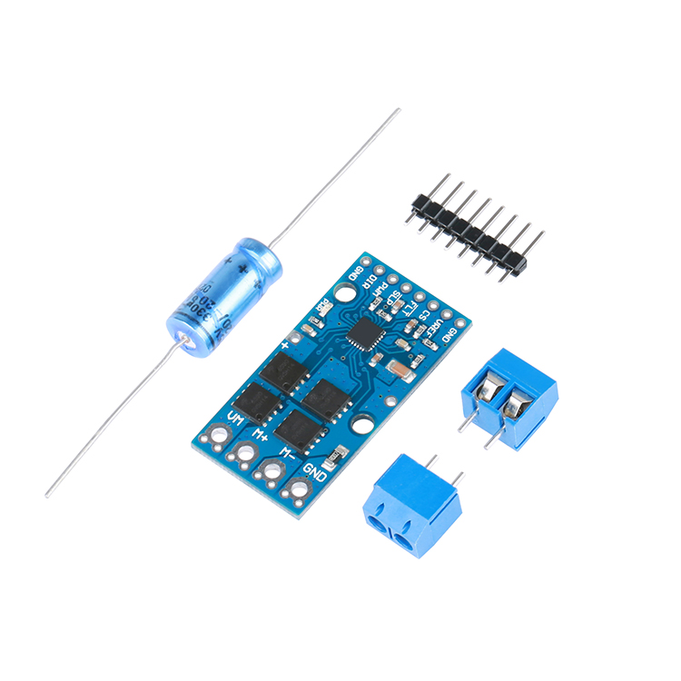
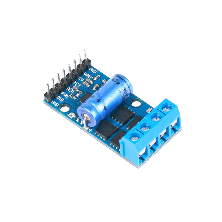
Motor drive 200W high power H bridge วงจร Drive Motor 5.9V to 30V 23A
| รหัสสินค้า | SKU-00444 |
| หมวดหมู่ | Motor Driver / Servo / Motor |
| ราคา | 650.00 บาท |
| สถานะสินค้า | พร้อมส่ง |
| ลงสินค้า | 16 ต.ค. 2560 |
| อัพเดทล่าสุด | 27 พ.ค. 2562 |
| จำนวน | ชิ้น |

รายละเอียดสินค้า
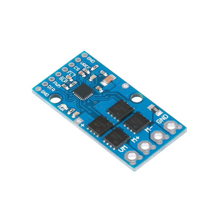
Motor drive is composed of a single H- bridge driver IC plus four external N- channel MOS tube.Support 5.9V to 30V wide voltage input, continuous current can reach 23A , support 100% pulse width modulation. Module through the direction of the DIR pin and speed PWM pin to achieve the motor is positive, reverse and speed control.
The control terminal supports 1.8V - 5V logic input, and the driver IC integrates the PWM current regulation function, thus limiting the motor surge current. When the SLP pin is set low, the MD04 drive module can enter the low power mode, resulting in a lower quiescent current loss of approximately 9uA .
Working voltage: 5.9 - 30V
Working current: 23A
Logic input: 1.8V , 3.3V , 5V ( max )
PWM frequency: 100kHz
Current detection: 50mV / A (valid only during forward or reverse rotation)
Reflective voltage protection: none ( VM and GND are not reversed)
Undervoltage protection: Yes
Short circuit protection: Yes
Control truth table
SLP pin default low, the normal use of the SLP pin need to set high, you can directly connected to the logic power of the positive, but also through the microcontroller IO port control.
| Motor drive truth table | |||||
| SLP | PWM | DIR | M + | M- | status |
| H | H (PWM) | H | H | L | Forward (PWM) |
| H | H (PWM) | L | L | H | Backward (PWM) |
| H | L | X | L | L | brake |
| L | X | X | X | X | Free to stop |
Note: The table H , L , respectively, said high and low level, the logic drive part of the maximum input voltage shall not exceed 5.5V . 1.8V , 3.3V , 5V system are applicable.
| Pin | Default state | description |
| VM | Power input, voltage range 5.9-30V (max) | |
| M + | Motor output wiring positive | |
| M- | Motor output wiring negative | |
| GND | Connect to the power supply negative | |
| PWM | Low level | Motor speed PWM signal input, you can achieve motor speed adjustment |
| DIR | Low level | Motor direction control, when high, the current flows from M + to M-, and vice versa from M-flow to M + |
| SLP | Low level | Low power mode, the default low level, the need to use the SLP pin to continue high |
| CS | The current sense pin is valid only when positive and negative, the output voltage is proportional to the current (50mV / A), and the current is zero when the voltage is 0.05V. | |
| Vref | Set the module maximum drive current, the default 30A |
PWM frequency
Motor drive up to 100KHz of the PWM frequency, it is noteworthy that the drive circuit and the switching losses will be proportional PWM frequency. So in general, we recommend using a 10 - 30KHz drive motor.
Current detection and current limiting
Motor driver current detection pin for the CS , the output voltage is proportional to the motor side current. Approximately 50mV / A , plus 50mV about offset, that is, when both ends of the motor current is zero, CS voltage pin is approximately 50mV ; when the CS terminal current reaches 10A when, V CS = 50mV / A * 10 + 0.05V = 0.55V . It should be noted that the current detection function will not detect the peak current generated by the motor starting and stopping instantaneously, only when the drive is operating in positive / reverse mode.
วิธีการชำระเงิน
ค่าจัดส่งสินค้า มีทั้ง แบบ พัสดุลงทะเบียน พัสดุด่วนพิเศษ (EMS) ,KERRY
สั่งสินค้าและแจ้งยอดชำระเงินพร้อมหลักฐานการโอนเงินก่อน (10.00 น.) ส่งสินค้าออกภายในวันเดียวกันหรือวันทำการถัดไปแล้วแต่กรณี
กรุณาแจ้งยอดโอนพร้อมแนบหลักฐานการโอนมาที่ http://roboticscircuitshop.lnwshop.com/informpayment
หรือ izemkung@gmail.com
กรุณาระบุชื่อผู้ซื้อ ธนาคารที่ทำการโอน เวลา
และOrder #ด้วยทุกครั้ง เพื่อความสะดวกและรวดเร็วในการจัดส่งสินค้า
ระบบของร้านจะแจ้ง
สถานะการสั่งซื้อ การชำระเงิน การส่งสินค้าและหมายเลขพัสดุให้ท่านทราบทางอีเมล์
กรุณากรอกรายละเอียดให้ครบถ้วน เพื่อความสะดวกในการจัดส่ง
ชำระเงินผ่านธนาคาร

LINE add Friend สแกนเเล้วติดต่อกับทางร้านได้โดยตรง
MEMBER
Join เป็นสมาชิกร้านค้า
